So here we are, and it's May 2017. This blog probably would have continued to be neglected were it not for someone asking me a question about repositioning the wind screen's well nuts. I am ashamed to admit that I have not had my butt in the saddle for...well, too long, except for riding to the dealer to get two recall notices and a state inspection taken care of. I am planning on rectifying this situation in the latter half of 2017 even if I have to just set a notice to go riding on my calendar.
Life Support for the Battery
The downside of the V-Strom sitting idle is that my battery had gone complete flat. Again. The place where I park it does not have power readily available, so putting it on a trickle charger really isn't an option. I found a solar panel battery tender that I thought would do the trick, but I wasn't really sure how I would route the wire into where I park the bike. For whatever reason over the past year since I bought it, I have completely overlooked the fact that there is a translucent skylight in the roof, which allows plenty of light for the solar panel to generate power. Just to be sure, I put my multimeter to it, and it read 17-18VDC at the leads. Bingo! Two nails and a hammer later, I now have the solar panel battery tender mounted up on the rafter just below the skylight, and all I need to do is install the charging pigtail on the battery so I can just plug it in when I get back from a ride. For those of you who are have a similar need, it is a Sunforce 12V Power Sports Battery Maintainer. Click on the link for more information. Please note that this is specifically to maintain a battery that already has a charge. If your battery has gone flat, then you will need to use a charger.
UPDATE: So due to some surgery at the beginning of 2018, I was unable to ride pretty much for the first half of the year. By the time I was recovered enough to do so, it was just too damned hot, and then I started a new job. In mid-October, I decided to go for a quick shakedown ride and was disappointed to find that my battery was dead, even though it had been connected to the solar battery maintainer. Apparently all the recent rainy days had conspired against me, and the solar panel was unable to keep up. So the lesson to be learned here is to occasionally check the battery even though it's on the maintainer or just disconnect it altogether. *sigh*
Upcoming Goodies to be Installed
As you may or may not recall, my wonderful wife bought me a Garmin Zumo 660 GPS, but despite the Zumo having a rechargeable battery, Garmin only provided the powered cradle for it. This left me without any means for mounting it until I made the time to figure out where to run the wires. I have since decided against a RAM mount solution and went with the SW Motech vibration damped GPS mount from Twisted Throttle. My original thought was to simply run the power to the AUX power port under the right fairing, but the Garmin cradle also includes additional wiring a 3.5mm headphone/audio jack and a 2.5mm mic jack as well as a mini-USB port for a traffic receiver antenna which is pretty useless for a motorcycle as it integrates with a 12V DC power plug. While I have bluetooth and won't really need the additional inputs/outputs, I thought it might be good to have available. There's still a part of me that's considering stripping open the primary cable casing, cutting off and sealing those other leads, and still running the power to the AUX power port. I can always buy a replacement Garmin cradle for $50.
The other item to be installed is a Givi side stand foot enlarger plate. This will help to keep the side stand from sinking into soft ground or dirt by providing a larger surface area. I had been meaning to do this since I bought the V-Strom, but I never got around to doing it. I figured it was time to fix this.
When I get around to installing these items, I'll be sure to post an update of the installations complete with pictures and any lessons learned. Until then, keep the rubber side down!
Showing posts with label accessories. Show all posts
Showing posts with label accessories. Show all posts
Friday, May 26, 2017

Friday, January 1, 2016
2015? Where did it go?!
Well, it seems that 2015 has managed to slip by without so much as an edit to the ole blog here. I believe that a lot of it is due to the fact that I didn't get to do any riding of note this year. During the late winter and spring, it seems that Fridays were the unofficial rain day of the week. Fridays were also the only free day that I had to go riding since I try to keep my weekends open so I can maximize time spent doing things with my wife and son, and I am a self-proclaimed fair-weather rider when I can manage it, i.e. like being caught in a random shower or expecting to ride in inclement weather as part of a roadtrip.
If it wasn't raining, then there would be some bit of administrivia requiring my attention during my day off, such as doctor visits, car maintenance appointments, or visits to the vet for my dog. The next thing I knew, it was the dead of summer, and while I'm not averse to warm weather riding, my level of enjoyment plateaus quickly when the ambient temperature is significantly higher than my body temperature. Don't get me wrong, I did take the bike out, but it would mainly be for a quick morning/lunch run and quick shot back via superslab. I was also able to get the V-Strom inspected during this time, which was only...6 months late.
Work then interfered for the remainder of the summer, and fall really has yet to manifest itself in Texas this year, so we'll probably go straight to winter. Work is no longer a hindrance as I've resigned and am pursuing new opportunities that are hopefully a lot more fun, but that's another story. Suffice it to say, the weather has again turned generally crappy. Crappy, except for those beautiful days while I was suffering from strep throat and then a cold which quickly followed. So timing-wise, riding wasn't really in the cards.
And now it's 2016. I am hopeful that 2016 will be a much better year for riding. For starters, my lovely wife bought me a new Garmin zumo 660LM GPS unit for the V-Strom! While not a necessity, I think it will make my life a lot easier since I'll have maps/navigation easily at my disposal rather than having to stop somewhere, take my gloves off, dig out my phone, and using my GPS apps from there. With the country and Farm-to-Market (FM) roads in Texas, there is really no telling what direction you will ultimately end up heading as they turn and wind around long-forgotten farm boundaries. Now I can just ride, make a random turn, and not really be majorly concerned about where I'm headed, because I can track my way back using the zumo, or I can simply instruct it to take me home.
I've only played with the zumo off-bike, but I've got it updated with the latest maps, customized the icon with a motorcycle, and tweaked the settings for how I think I would like it to work. One of the things I have to figure out is how I want to handle the bluetooth pairings, which I think will involve re-reading a few manuals. In addition to my iPhone, there's the Scala Carda G9, and now the Zumo. I currently have the phone paired with the G9, but the G9 can be the hub and also pair with the zumo, or the zumo can be the hub and pair with the phone and the G9. I'm currently inclined to use the G9 as the hub even though it would be nice to use the zumo for playing MP3s since it could be controlled from the touch screen. I think the G9 is the better hub option mainly for this reason: if for some reason I should be thrown off of the motorcycle beyond BT range, the G9 would still theoretically be paired to the iPhone (assuming it has survived the unexpected dismount and is still operational in my pocket), and I could initiate an emergency call. If the zumo is the hub, then the G9 would no longer be able to find the iPhone for emergency calls. I will, of course, have to validate this assumption, but that's currently where my head is.
Before any of that can happen, though, I need to get this bad boy installed on the bike. I have an auxiliary power pigtail that I bought from Eastern Beaver, which will plug directly into the V-Strom's auxiliary power port, which is bundled up inside the right front fairing. It should be a simple matter of plugging it in and then splicing the power leads from the zumo cradle to the pigtail. The zumo came with all of the RAM mount hardware necessary to mount the unit using a RAM ball system, and I fortunately have two 1" RAM ball mounts on the handle bar courtesy of the Adventure Tech mirror extenders. I will probably go with this option first just for proof of concept, but I am considering buying the AdventureTech GPS mounting plate that goes under the windshield to mount the GPS unit front and center above the dash. My understanding is that it makes it a lot easier to use with a quick glance. As long as I'm doing all that, I may also get an AdventureTech auxiliary shelf to mount a voltmeter and AUX power outlet, but since I don't have anything that currently requires power, I may hold off on this since my actual needs might vary from what I choose now.
At any rate, those are my first thoughts of the new year. Look for an update in the near future for however I decide to mount the zumo. I'll probably document both the temporary mounting using the bar RAM mounts and then the final mounting using the dash plate.
I hope 2015 treated you better than it did me, and here's looking forward to a much improved 2016!
If it wasn't raining, then there would be some bit of administrivia requiring my attention during my day off, such as doctor visits, car maintenance appointments, or visits to the vet for my dog. The next thing I knew, it was the dead of summer, and while I'm not averse to warm weather riding, my level of enjoyment plateaus quickly when the ambient temperature is significantly higher than my body temperature. Don't get me wrong, I did take the bike out, but it would mainly be for a quick morning/lunch run and quick shot back via superslab. I was also able to get the V-Strom inspected during this time, which was only...6 months late.
Work then interfered for the remainder of the summer, and fall really has yet to manifest itself in Texas this year, so we'll probably go straight to winter. Work is no longer a hindrance as I've resigned and am pursuing new opportunities that are hopefully a lot more fun, but that's another story. Suffice it to say, the weather has again turned generally crappy. Crappy, except for those beautiful days while I was suffering from strep throat and then a cold which quickly followed. So timing-wise, riding wasn't really in the cards.
And now it's 2016. I am hopeful that 2016 will be a much better year for riding. For starters, my lovely wife bought me a new Garmin zumo 660LM GPS unit for the V-Strom! While not a necessity, I think it will make my life a lot easier since I'll have maps/navigation easily at my disposal rather than having to stop somewhere, take my gloves off, dig out my phone, and using my GPS apps from there. With the country and Farm-to-Market (FM) roads in Texas, there is really no telling what direction you will ultimately end up heading as they turn and wind around long-forgotten farm boundaries. Now I can just ride, make a random turn, and not really be majorly concerned about where I'm headed, because I can track my way back using the zumo, or I can simply instruct it to take me home.
I've only played with the zumo off-bike, but I've got it updated with the latest maps, customized the icon with a motorcycle, and tweaked the settings for how I think I would like it to work. One of the things I have to figure out is how I want to handle the bluetooth pairings, which I think will involve re-reading a few manuals. In addition to my iPhone, there's the Scala Carda G9, and now the Zumo. I currently have the phone paired with the G9, but the G9 can be the hub and also pair with the zumo, or the zumo can be the hub and pair with the phone and the G9. I'm currently inclined to use the G9 as the hub even though it would be nice to use the zumo for playing MP3s since it could be controlled from the touch screen. I think the G9 is the better hub option mainly for this reason: if for some reason I should be thrown off of the motorcycle beyond BT range, the G9 would still theoretically be paired to the iPhone (assuming it has survived the unexpected dismount and is still operational in my pocket), and I could initiate an emergency call. If the zumo is the hub, then the G9 would no longer be able to find the iPhone for emergency calls. I will, of course, have to validate this assumption, but that's currently where my head is.
Before any of that can happen, though, I need to get this bad boy installed on the bike. I have an auxiliary power pigtail that I bought from Eastern Beaver, which will plug directly into the V-Strom's auxiliary power port, which is bundled up inside the right front fairing. It should be a simple matter of plugging it in and then splicing the power leads from the zumo cradle to the pigtail. The zumo came with all of the RAM mount hardware necessary to mount the unit using a RAM ball system, and I fortunately have two 1" RAM ball mounts on the handle bar courtesy of the Adventure Tech mirror extenders. I will probably go with this option first just for proof of concept, but I am considering buying the AdventureTech GPS mounting plate that goes under the windshield to mount the GPS unit front and center above the dash. My understanding is that it makes it a lot easier to use with a quick glance. As long as I'm doing all that, I may also get an AdventureTech auxiliary shelf to mount a voltmeter and AUX power outlet, but since I don't have anything that currently requires power, I may hold off on this since my actual needs might vary from what I choose now.
At any rate, those are my first thoughts of the new year. Look for an update in the near future for however I decide to mount the zumo. I'll probably document both the temporary mounting using the bar RAM mounts and then the final mounting using the dash plate.
I hope 2015 treated you better than it did me, and here's looking forward to a much improved 2016!
Saturday, May 31, 2014
MRA X-creen Wing Replacement
If you've read my previous posts, you know that I bought my MRA X-creen second hand. Once I got it mounted properly and the wing adjusted to my liking, I have really liked it. I did notice that there were a couple of tiny cracks around the screws that clamped the mounting hardware to the wing itself, but I accepted that as part of purchasing on the secondary market as well as part of the significant cost savings. Over time, the cracks have increased significantly to the point that I became concerned that the wing might eventually break loose.


I went to the MRA website (www.mra.de/en) to see about ordering a replacement part, but I only found where you can order the entire X-creen. I clicked on the Contact link and submitted a request for pricing on a replacement wing, and I received a reply from Nicole asking me to send her pictures of the wing and the cracks as they may be able to replace the part free of charge. I sent her the pictures (shown above), and she sent me another email saying that they would replace the wing for free! I love it when a company stands behind their products, no questions asked.
The part arrived a little over a week later, and instead of just the clear plastic wing, it was the wing plus the mounting hardware that is screwed onto the wing.
When I went to replace the wing, I couldn't really see how the locking mechanism came apart. Mentally, I had an idea of how it should go together just based on how the locking mechanism works, but I didn't want to force anything and break something else. I went back to the MRA site and started looking at the installation instructions for their other products that use the same mechanism and finally found an exploded diagram of the locking mechanism. As it turns out, it is assembled as I had visualized it, and the diagram and associated instructions confirmed my suspicion that the pieces simply snap into place.
 |
| X-creen Mounting Hardware - Exploded Diagram |
The key to the whole thing is part 2, which is the locking knob for adjusting the angle of the wing itself. The instructions said to turn it so that it is in the open position (parallel with the length of the shield), but I found that it would not budge. When I turned it to the locked position (perpendicular to the length of the shield), it came out fairly easily.
After removing the locking knob on the other side, it was a simple matter of removing the shield from the arms. You need to be careful when removing the shield, because part 4 will be loose and can fall out of the arm. This is the piece that the locking knob slots into in order to lock the shield into place.
Installation of the new wing was a simple matter of reversing the steps above. I found that I had to pinch the locking mechanism at part 4 and the outside of the new wing in order to get the locking pin to insert fully. This makes sense since the pin serves that very function. With the arms and wing adjusted back to what I believe is their original positions, everything is ready to go again.
I want to thank Nicole at MRA for the excellent customer service!
Friday, May 31, 2013
MRA-Xcreen Update -- Wing Position and Air Flow
Just a quick update here. I had a chance to take the bike out for a couple of hours today and play with a number of different positions for the wing on the X-creen. I had originally been riding with the support arms pretty much straight up 12 o'clock with the top of the wing angled slightly backward since this is how it appeared in the pics from MRA. This worked pretty well, and after installing the spacers, it even seemed to work better. After several starts and stops to test various positions, I've now settled on having the support arms positioned so they are pointing directly forward with the top of the wing angle back so it's almost, but not quite, parallel to the primary shield. It's probably about two clicks away from being parallel. Sorry, I didn't take any pictures, since it was a trial-and-error process. If you want a picture of the final position, leave a comment, and I'll go take one and add it to this post.
It was fairly windy today, with the winds blowing out of the south, so I was able to test the position with and without a headwind as well as with crosswinds. This new position seems to push the air high enough that the air intakes on the top of my Shoei RF-1000 can catch it, but it leaves the helmet itself alone. I'm not sure, but I think this works better than the original position due to the wing being further forward.
I have also come to the conclusion that the primary source of any buffeting is now the mirrors. Installing the mirror extenders helped tremendously, so I may experiment with angling the mirror stalks in a little more to see if that helps. I also considered buying some Saeng Micro-Swirl Generating Edging and putting it on the front of the mirrors to see if that helps. Then again, the temperatures are quickly ratcheting up into the 90s, so it's probably worth it to have a bit of wind for evaporative cooling.
UPDATE: At the request of Mark Collins, I took a picture of my current wing position setting for your reference. As you can see, the support arm is pointing directly forward, almost parallel to the ground. The wing is angled at about 45 degrees from the arm, which gives it a little upward angle relative to the primary shield. In case you missed it in the original X-Creen post, I'm 6'-0" with a 32" inseam, so your mileage may vary with this setup.

It was fairly windy today, with the winds blowing out of the south, so I was able to test the position with and without a headwind as well as with crosswinds. This new position seems to push the air high enough that the air intakes on the top of my Shoei RF-1000 can catch it, but it leaves the helmet itself alone. I'm not sure, but I think this works better than the original position due to the wing being further forward.
I have also come to the conclusion that the primary source of any buffeting is now the mirrors. Installing the mirror extenders helped tremendously, so I may experiment with angling the mirror stalks in a little more to see if that helps. I also considered buying some Saeng Micro-Swirl Generating Edging and putting it on the front of the mirrors to see if that helps. Then again, the temperatures are quickly ratcheting up into the 90s, so it's probably worth it to have a bit of wind for evaporative cooling.
UPDATE: At the request of Mark Collins, I took a picture of my current wing position setting for your reference. As you can see, the support arm is pointing directly forward, almost parallel to the ground. The wing is angled at about 45 degrees from the arm, which gives it a little upward angle relative to the primary shield. In case you missed it in the original X-Creen post, I'm 6'-0" with a 32" inseam, so your mileage may vary with this setup.

Friday, May 17, 2013
MRA X-creen Re-mount or "Oops, need to RTFM!"
So here's a bit of a lesson in RTFM. That would be Read The Farkle's Manual in this case. Now in my defense, I didn't read it, because I didn't know about it. If you read my original post, you'll know that I bought this screen second-hand from a fellow Stromtrooper. When I opened the package, all I saw was the windshield itself, so I figured it was just a direct replacement, using the stock screen's screws to mount it. Apparently that is not the case. As I was throwing out boxes that have accumulated, I was separating out the packing material that could not be recycled, and lo and behold, there was a plastic ziplock bag at the bottom of the box with... you guessed it... the installation sheet and some parts!
The parts baggy included two 15mm plastic spacers, two 10mm plastic spacers, washers, and longer screws with which to mount the windshield. Interestingly enough, I was contemplating going to the hardware store to look for these very items to see if that would help move the wind off the top third of my helmet. I installed the parts today before I went for a ride, which took all of 15 minutes. The key to installation is to put the washer on the screw, then insert the screw through the front of the windshield. On the back side of the windshield, put the spacer on the screw, and then put the well nut on the screw and turn it 2-3 times to keep it from falling off, but not far enough to compress the rubber. The two long screws go with the 15mm spacers in the top holes. The short screws go with the 10 mm spacers in the bottom holes. Once all four screws and spacers are installed, it's a simple matter of pushing the well nuts into the holes in the fairing and tightening them down with the included allen wrench (3mm).
I was very surprised at how much of a difference it made. I can still hear some wind roar with my ear plugs, but I don't really think that's going to ever go away, but the main thing is that there is minimal turbulence hitting my head now. I had been considering trying out a Parabellum windshield, but I don't think that's necessary any more. The main reason I know it's made a difference is because there is quite a bit less wind noise being picked up by my helmet-mounted Drift HD.
I still need to play around with the angle of the spoiler, though. I angled it back two clicks from the straight up position, and it seems to have improved things a little bit. I'm going to rotate it forward one click to see how that changes things, or perhaps rotate the arm forward to move it down and out front a bit more to see what that does. Overall, the proper mounting pieces have improved this windshield, and I thought it was pretty good to begin with.
 |
| The mounting parts are essential for proper fit. |
 |
| Back side of the windshield with all screws, spacers, and well nuts fitted. |
I still need to play around with the angle of the spoiler, though. I angled it back two clicks from the straight up position, and it seems to have improved things a little bit. I'm going to rotate it forward one click to see how that changes things, or perhaps rotate the arm forward to move it down and out front a bit more to see what that does. Overall, the proper mounting pieces have improved this windshield, and I thought it was pretty good to begin with.
Friday, January 4, 2013
MRA X-creen
As I've been riding, I've noticed that the wind buffets the top-third of my helmet at highway speeds. Raising the windshield didn't really seem to make much of a difference, so I started looking into different aftermarket solutions. I'll save everyone the pain of reading through my thought process and just say that I decided on the MRA X-creen, which is similar to the Suzuki V-Strom Adventure Touring Screen, except the wing on the X-creen is attached with a single arm on both sides (vs. two), which allows it a greater range of motion. I got a great deal on mine after seeing it for sale on the Stromtrooper.com For Sale forum. It cost me $115 shipped, which is a great deal considering TwistedThrottle advertises it for $209.99 before shipping.
Installation of the windshield is very simple, requiring only a 3mm allen wrench. Simply remove the four screws, remove the stock windshield, and mount the X-creen in its place. I left the X-creen in the top position where I had the stock windshield. The X-creen with the wing in the lowest position is approximately the same size as the stock screen. Raising the wing makes the X-creen quite a bit taller. I would guess approximately 2-3".

Because the X-creen does not have the built-in stand-offs like the stock screen, it sits quite a bit closer to the instrument pod and is raked further back as well. It's more like the screen was on my old Ninja 650R. You can see the direct comparison in the pictures below. It looks like the Suzuki Touring Screen may be designed to provide a positioning similar to the stand-offs. I would have liked to try it, but they want almost $300 for it!
NOTE: Please be sure to read my update on the X-creen installation here.
Seeing as how I do not own or have access to a wind tunnel, I had to take the bike out and make a lot of runs up and down the freeway frontage road to make my adjustments to the wing. I started out in the position you see above, but I got as much if not more wind blast to the helmet. I then tried adjusting the wing angle, but it didn't do enough. So I then flipped the arm into the upright position so that the wing was in the highest position. When the arm is upright, you cannot adjust the wing to be more vertical, only more horizontal, so I ended up adjusting the arm to get the wing more vertical to move the airflow higher.
After several stops and adjustments, I think I've found a good setting that gets most of the turbulent air to go over my helmet. The arm is pretty much vertical, and the wing is rotated back about 20 degrees. Just for reference, I am 6'-0" with a 32" inseam, and I'm riding on the stock height seat.
 |
| MRA X-creen (Photo from TwistedThrottle.com) |

Because the X-creen does not have the built-in stand-offs like the stock screen, it sits quite a bit closer to the instrument pod and is raked further back as well. It's more like the screen was on my old Ninja 650R. You can see the direct comparison in the pictures below. It looks like the Suzuki Touring Screen may be designed to provide a positioning similar to the stand-offs. I would have liked to try it, but they want almost $300 for it!
NOTE: Please be sure to read my update on the X-creen installation here.
 |
| Stock Screen Profile View |
 |
| MRA X-creen Profile View |
 |
| Final Arm/Wing Position |
I no longer feel like someone's pushing to top of my helmet side to side, but it's not like I'm riding inside my car, either. I will still be wearing ear plugs to dampen the wind noise. I'm sure more adjustment will be required, because there was a good 10-15 mph wind yesterday. Unfortunately, the forecast is pretty much crappy for the next few days, so it will probably be a while before I can get out for an extended ride to see how well this screen does long-term. Until then, I think it's a keeper.
UPDATE: Please be sure to read my follow-up posting on the X-creen and my posting on replacing the wing/spoiler.
UPDATE: Please be sure to read my follow-up posting on the X-creen and my posting on replacing the wing/spoiler.
Wednesday, November 21, 2012
RAM Mounts for the Drift POV Cam
I like having my POV cameras going when I ride for two reasons. The first is to be able to create a video of my ride if it's particularly interesting that day. The other is for documentation just in case the something happens. Lately, I've been riding with only one of my cameras mounted to the side of my helmet, which quite frankly, makes for some nausea inducing footage, particularly when checking around for lane changes or making turns. It is probably a preferred mounting point for the second of the above reasons, though, as I'm more likely to see things at least from the front cone of vision.
I've been thinking of mounting points on the bike itself, and the two obvious locations are the mounting posts for the frame sliders and the passenger footpeg supports for a rear-facing camera. Unfortunately, the handle bar mount that came with my Drift Innovation HD170 Stealth POV cam is for a 1" diameter bar, and the footpeg supports are smaller than that. That meant buying a new mount. RAM Mount makes a U-bolt mount that will fit anywhere from a 0.5" to 1.25" bar. Perfect. The part number for the base is RAM-B-231ZU, and I got ordered it through Amazon.com with 2 Day delivery since the vendor was part of Amazon Prime. I also had to order another camera mount as well as a double-socket arm so that I could mount both cameras simultaneously. I already had one set from a previously purchased mount. The camera mount is RAM-B-202AU and the arm is RAM-B-201U. These also came from Amazon. Here are the Amazon links for the mount and arm.
Tools Used:
Time to Install: ~45 minutes
I installed the U-bolt mount shown above on the upper support tube for the left rear passenger footpeg. The insert on the left will swivel around the support to find its preferred position to take advantage of the V-shaped grooves for grip. I used the 7/16" socket and ratchet to tighten the nylock nuts until they were snug. A good tug on the double-socket arm confirmed that the mount did not slip or shift positions.
With the RAM Mount fully assembled, it was a simple task to mount the camera and position it. After mounting the camera, I sat on the bike to make sure that my leg would not bump into the camera. Even with the camera positioned towards the front of the bike as shown below, there was not interference with my left leg.
For the forward facing location, I contacted Blair at SVRacingParts.com to find out the diameter of the post. Blair said they are 32mm, which is 1.259". Unfortunately, the RAM mount U-bolt solution only goes up to 1.25", and I was pretty sure that .009" would make a difference. I bought their base that uses a metal strap clamp like what is used on rubber hoses, and it comes with the U-bolts as well, so I could check first to see if that would work. It didn't. The part number is RAM-B-231Z-2U. I got this through Amazon.com as well, although this part wasn't from an Amazon Prime vendor. The package came with the U-bolts as well, so I test fitted the large U-bolt to the post and, as expected, it was too small. Even if I had pried it appart, the rounded portion of the bolt would never fit around the post, and I didn't want to mess up the finish while attempting it. I've since been in contact with Blair, and he said he would see what they could do to accommodate the RAM Mount in future production runs.
The base of this mount is a bit wider than the length of available mounting post for the frame slider. The edge of the base closest to the frame actually sits up on top of the washer that sits between the mounting post and the spacer. I was hoping to orient the base so that the ball mount is actually away from the frame, but if you do that, the metal clamping strap sits right on top of the washer, which is not ideal. So I turned it around such that the ball mount is next to the frame and the strap can cinch around the aluminum post. Be sure to measure the rubber strap cover before putting it on the metal strap as it will need to be cut shorter than it is. If you leave it at its original length, you won't be able to fully tighten the strap.
After taking this picture, I sat on the bike and found that the front camera hit my shin pretty easily. I ended up having to loosen the metal strap to rotate the mount so the ball mount was pointing a little bit forward. If you look from the end of the slider puck, the ball is pointing between 10 and 11 o'clock. I also angled the double-socket arm forward a bit, too, which got it away from my leg, but also brought it in a bit closer to the bike than I originally wanted. I may look at getting a second double-socket arm for more adjustability.
With everything mounted and connected now, I took the bike out for a shakedown ride as well as to burn off some more break-in miles. I had both cameras going on the RAM Mounts instead of having the forward facing camera on my helmet mount. The resulting video was quite stable and showed only the slightest amount of rolling shutter/Jell-O effect. Sorry about the first 25 seconds or so of non-action while putting on my gloves. I just edited the video on YouTube to cut that out, but it doesn't seem to have updated fully yet.
When I got back from my ride, I found that I had just hit the 500 mile mark! With the initial break-in stage completed, I can now rev up to 7,500 rpm, which will make leaving stop signs and lights a lot easier, not to mention avoiding getting run over on the highways!

I hope these posts have been at least interesting if not helpful. Please feel free to leave comments.
I've been thinking of mounting points on the bike itself, and the two obvious locations are the mounting posts for the frame sliders and the passenger footpeg supports for a rear-facing camera. Unfortunately, the handle bar mount that came with my Drift Innovation HD170 Stealth POV cam is for a 1" diameter bar, and the footpeg supports are smaller than that. That meant buying a new mount. RAM Mount makes a U-bolt mount that will fit anywhere from a 0.5" to 1.25" bar. Perfect. The part number for the base is RAM-B-231ZU, and I got ordered it through Amazon.com with 2 Day delivery since the vendor was part of Amazon Prime. I also had to order another camera mount as well as a double-socket arm so that I could mount both cameras simultaneously. I already had one set from a previously purchased mount. The camera mount is RAM-B-202AU and the arm is RAM-B-201U. These also came from Amazon. Here are the Amazon links for the mount and arm.
Tools Used:
- Ratchet Handle
- 7/16" Socket
- Cordless Screw Driver with Flat Head Bit
- Flat Head Screw Driver
Time to Install: ~45 minutes
 |
| RAM-B-231ZU U-Bolt Mount |
 |
| Mount Installed on Rear Passenger Footpeg Support |
 |
| Drift POV Camera Mounted Facing Rear |
The base of this mount is a bit wider than the length of available mounting post for the frame slider. The edge of the base closest to the frame actually sits up on top of the washer that sits between the mounting post and the spacer. I was hoping to orient the base so that the ball mount is actually away from the frame, but if you do that, the metal clamping strap sits right on top of the washer, which is not ideal. So I turned it around such that the ball mount is next to the frame and the strap can cinch around the aluminum post. Be sure to measure the rubber strap cover before putting it on the metal strap as it will need to be cut shorter than it is. If you leave it at its original length, you won't be able to fully tighten the strap.
 |
| Metal Clamping Strap Cinched Tight |
 |
| Drift POV Camera Mounted Facing Forward |
 |
| Drive POV Cameras Mounted Fore and Aft |
With everything mounted and connected now, I took the bike out for a shakedown ride as well as to burn off some more break-in miles. I had both cameras going on the RAM Mounts instead of having the forward facing camera on my helmet mount. The resulting video was quite stable and showed only the slightest amount of rolling shutter/Jell-O effect. Sorry about the first 25 seconds or so of non-action while putting on my gloves. I just edited the video on YouTube to cut that out, but it doesn't seem to have updated fully yet.
When I got back from my ride, I found that I had just hit the 500 mile mark! With the initial break-in stage completed, I can now rev up to 7,500 rpm, which will make leaving stop signs and lights a lot easier, not to mention avoiding getting run over on the highways!

I hope these posts have been at least interesting if not helpful. Please feel free to leave comments.
Connecting the Givi Maxia 3 Brake Lights with help from Eastern Beaver
The Givi Maxia 3 Luxury B top case came with the padded liner as well as the brake light kit pre-installed. There are some things that are commonly accepted regarding the Givi brake light kit:
Tools Used:
Now I had to install a connector housing on the auxiliary lead, which would be used to connect the Givi brake light. Interestingly enough, the male pins go in the female housing, and the female pins go in the male housing. To keep with the factory installation, I put a female housing on this lead, which meant that I had to install the male leads on the ends of the wires. After crimping on the leads, I inserted them into the housing so that they matched the factory configuration. The only difference is that I had to use the 6th pin for the red (brake light output) wire, where the factory plug only uses 5 pins.
I wanted to route the Givi brake light lead in such a fashion that it would remain stable and wouldn't have much of a chance of being snagged by anything. I removed the top cover of the mounting plate and wove the wire through one of the holes and back down so that it would take any strain from being tugged instead of the directly at the connector pod.
I then ran the cable across to the left side under the factory rack, wound it around the rack's left front mounting post, across to the rack's right mounting post, and then down the side of the rear panel to bring the cable inside the rear body panel via the hole for the exhaust's mounting point. Inside the tail section, I used a cable tie to secure the Givi brake light lead to the subframe.
With the lead inside the tail section, I could put the male connector on it. This required crimping the female pins to the lead wires. Again, since I had the Version 2 EB connector, I had to install the red jumper wire to connect the brake light input and output wires so that the motorcycle's tail light would work as well as the Givi brake lights. After inserting the pins into the housing, I plugged everything together, powered on the motorcycle, and tested everything to make sure all the lights were working, especially the brake lights on the motorcycle and the case. Everything checked out fine.
With all the lights verified as working correctly, I simply tucked the auxiliary lead underneath the crossbar in the under seat tray where the seat lock is mounted to keep it safe and out of the way.
The nice thing about going to this level of effort is that if I decide to install the Admore brake/turn/signal light upgrade on the Maxia 3, all I have to do is unplug the Givi lead, re-pin the male connector housing with the Admore lead, and plug it in. It's a $140 upgrade, so I'm not sure if I would do that or just install one of their light bars so that I have that extra visibility regardless of whether or not the top case is being used.
- The contacts in the case itself suck and result in intermittent contact, which in turn makes the brake lights sometimes work and sometimes not. So far, mine seem to be holding up well, but this may be a time will tell kind of issue.
- The wire taps provided to splice the brake lights into the bike's wiring harness suck.
- It's a pain to get to those wires, so you may as well splice it properly before putting it all back together.
- The Givi LEDs are somewhat hard to see during the day, but are quite visible at night.
So with all this in mind, I did more research on how best to connect the brake light when I came across Jim Davis' Eastern Beaver Power page, specifically the V-Strom products page. Apparently, all V-Stroms use a wiring harness for the brake, tail, and turn signal lights, which connect to the main electrical harness towards the rear of the subframe inside the left rear side panel. Jim makes a harness that will patch in at this connection, using the same type of plugs, and provides an auxiliary set of wires with which to control another set of lights, such as the Givi brake lights. I went with the Version 2 harness as it seemed the most flexible in case I want to install some different types of brake lights, and I also purchased additional plug housings so that I could have a clean factory-like installation instead of wire nuts or posi-taps. The plug housings are the Sumitomo 6-wire .090 HM-series connectors, or part number 6P090-HM on the Eastern Beaver site.
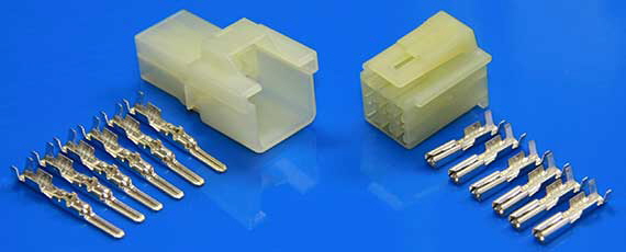 |
| 6P090-HM Connector |
- Wire Stripper/Cutter
- Crimping Tool
Time to Install: ~1 hour (I was taking my time with the wire stripping and crimping so as not to screw anything up.)
So the first thing I had to do was determine which way I needed to mount the contact lead for the Givi brake lights in the mounting plate. There are two contacts, but neither are marked. I installed the contact pod into the mounting plate with the wires coming out towards the front of the bike. Then I mounted the top case on the bike and connected the two wires to a 9V battery to see which combination of +/- would make the lights go on. As it turned out, the contact pod was installed such that the black wire was the ground (-) and the blue was the signal (+).
Now I took the Eastern Beaver (EB) harness and plugged it in-line with the factory wiring harness for the brake/tail/turn signal lights. Fortunately, it's very easy to separate the connectors by pressing down on the top of the male housing and pulling apart the plugs. The main harness (front of the bike) has the female connector, and the rear light harness has the male connector. With the EB harness in place, I turned on the power to the motorcycle in order to confirm that all the lights were working as expected. I had to cross-connect the purple and red wires, because the Version 2 EB harness has separate brake input and output wires to allow the installation of in-line brake light modulator units. If there isn't such a unit installed, then these two wires need to be connected so that the stock brake light still works.
 |
| Eastern Beaver Harness plugged into OEM Harness |
 |
| Plug Mounted on Auxiliary Lead |
 |
| Givi Brake Light Lead Under the Rack |
 |
| Givi Brake Light Lead Routed into Tail Section Through Exhaust Mount Hole |
 |
| Plug Mounted on Givi Brake Light Lead with Jumper |
 |
| EB Wiring Harness Tidied Up |
At any rate, I now have the added visibility of the Givi brake lights in the top case.
Tuesday, November 20, 2012
Installing the OEM Hand Guards and Raising the Windscreen
The next items up are the Suzuki OEM hand guards, which also came from www.oneidasuzuki.com. While not as robust as the Barkbusters, they're also not as expensive and serve my intended purpose, which is primarily to keep small road debris off my hands as well as the cold winter winds when it actually gets cold here in Texas. Having installed the OEM under cowling already, I've come to the conclusion that Suzuki's accessory installation instructions are actually quite good. They even include mentioning the one thing of note when installing the OEM hand guards is this: Loosen the screw holding the bar end weight, but do not remove the screw completely. You only need to loosen the screw enough so that you can pull the whole bar end weight assembly from the handlebar. If you do remove the screw all the way, it is quite likely that you will push the nut further into the handlebar, making it very difficult to remove. I actually learned this lesson the hard way when I was helping a friend install these on his '09 V-Strom.
Tools Used:
With the pivot pin removed, it's a simple matter of rotating it so that the clutch cable comes out of the groove in the end of the lever, freeing the cable stop.
 |
| Bar End Weight Assembly Removed |
- Phillips Head Screw Driver
- 10mm socket
- Adjustable Wrench
Time to Install: ~1 hour
Starting with the left (clutch) side, I removed the clutch lever pivot pin by first removing the nut and then unscrewing the pivot pin. From what I can tell, the nut on the bottom primarily serves to lock the pivot pin in place, but should the nut come off for whatever reason, the pivot pin would not simply pull free. The stock pivot pin will not be re-used.
 |
| Clutch Pivot Pin Nut |
 |
| End of the Clutch Lever where the cable inserts. |
The next step is to remove the cable from the lever mount and tension adjuster. I removed the tension adjuster completely by unscrewing it from the lever mount, but as it turns out, this was not necessary. All you really need to do is line up the slots to pull the cable free, and then pull the cable housing from the end of the adjuster screw. By not removing the adjuster, you won't have to re-adjust the tension on the clutch cable when you re-assemble everything.
With the clutch cable free, remove the stock boot and replace it with the boot included with the Hand Guards. The stock boot will not be re-used.
Using the replacement clutch-side pivot pin, re-assemble the clutch lever. (Be sure you press in the sensor switch before you try inserting the clutch lever, or it will not go in. This is the safety switch that will prevent you from starting the engine unless the clutch lever is pulled in.) The replacement pivot pin will screw in just like the stock pivot pin. The washer and spacer go on the bottom side of the lever. Re-use the stock nut. There isn't any need to use Locktite as the nut has an e-clip to prevent it from backing off.
With the replacement pivot pin in place, it is time to install the clutch-side hand guard. Before doing so, you need to remove the bar end weight assembly as described above. Loosen the screw about 4 turns, just enough to ease the pressure on the compression nut. Then work it side-to-side while pulling on the weight until it pops out. It took a good amount of pulling before mine came out. Now disassemble the bar end weight assembly completely, and re-assemble it using the included screw, which is much shorter than the stock screw. Insert the screw into the bar end weight, then slide on the included spacer with the smaller diameter end towards the weight, then the stock washer and finally the stock compression nut. The stock screw and aluminum sleeve spacer will not be re-used. Insert the newly re-assembled bar end weight assembly into the handlebar but do not tighten yet.
Take the left (clutch) side hand guard, and mount it on the pivot pin. There's a hole in the top that goes over the top of the pivot pin, and a slot that will go around the bottom of the pivot pin.
Secure the top of the hand guard using the included washer and cap nut. The outside of the hand guard will snap into place in the groove provided by the smaller end of the spacer. With the end of the hand guard snapped into place, tighten the bar end weight assembly screw to tighten the compression nut, holding the assembly in the handle bar.
Finally, secure the bottom of the hand guard to the pivot pin using the supplied washer and nut. Again, this nut has an e-clip in it to prevent it from back off by itself.
Installing the right (brake) side hand guard is essentially the same process, so I won't go into the whole process again. This side is actually easier, because you do not have to remove any cables, just replace the pin on the brake lever. The key difference is that the replacement pivot pin is different and uses a screw to secure the top of the hand guard. The top is a little crowded due to the cable assembly, but I was able to rotate them upward enough to remove the stock pivot pin and insert the replacement pivot pin.
Installing the Brake-side Hand Guard is a little trickier, because both the top and the bottom are slotted, so you have to hold the guard in place while trying to get the screw to go in. It might be a little easier to start the screw first, but you still would have to contend with the washer. Be sure the push the hand guard into place while tightening the screw as the screw will want to squeeze the hand guard out of position. Do not overtighten the screw, and you shouldn't have this problem.
The torque values on these nuts are very low, so it should be enough to tighten them until they are nice and snug. I used my torque wrench on the first two and despite using the recommended values, I think they still may have started to strip before I even got the click. So for the rest of them, I simply got them nice and snug. Fortunately, we're not dealing with engine mounting bolts or anything like that. The pivot pins are screwed in and the nuts are for locking purposes. Even then, they're captured by the hand guards themselves and then locked into place by the nuts securing the hand guards, so I don't think there's any real danger if any of the nuts did strip. The hand guards seem to be attached quite securely, and the levers work as well as before the installation.
The other thing I wanted to do was to raise the windshield from the stock middle position to the top position. The wind seems to be directed towards the top 1/3 of my helmet, resulting in quite a bit of buffeting and noise. Despite that, it's still better than what I got on my Ninja 650R, which was the air blast directed at my shoulders and a lot of noise from under the helmet and from being totally in the air flow.
Tools Used:
Removal is a simple matter of loosening the four screws using a 3mm hex driver and pulling the wind shield free.
After removing the windshield, I removed the four plugs from the top position holes. It took a bit of prying around the edges, but they finally came free.
Next, I removed the well nuts from the stock middle holes and moved them to the top holes. I found that they came out and inserted quite easily using a twisting motion.
All that was left to do was position the windshield over the well nuts and tighten the screws. I finger-tightened them first, centered the windshield, and then tightened the screws until they were snug. I gave the windshield a good push on the sides to make sure it wasn't going to shift positions. And that completes the major modifications to the V-Strom for now.
 |
| Clutch Cable Adjuster with grooves lined up. Cable housing inserts at the top. |
 |
| Clutch Cable with new boot. |
 |
| Clutch-side Replacement Pivot Pin Note the spacer that only goes on this side. |
 |
| Replacement Pivot Pin installed |
 |
| Washer, Spacer, and Stock Nut |
 |
| Re-assembled Bar End Weight Assembly |
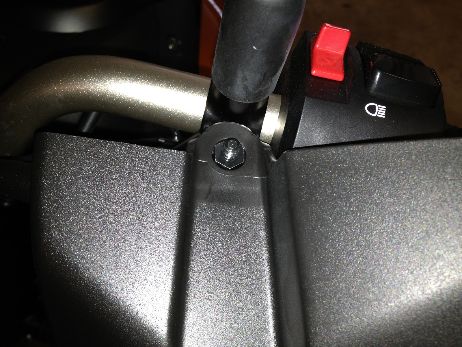 |
| Top of Clutch-side Hand Guard |
 |
| Bar End Weight Assembly with Hand Guard |
Installing the right (brake) side hand guard is essentially the same process, so I won't go into the whole process again. This side is actually easier, because you do not have to remove any cables, just replace the pin on the brake lever. The key difference is that the replacement pivot pin is different and uses a screw to secure the top of the hand guard. The top is a little crowded due to the cable assembly, but I was able to rotate them upward enough to remove the stock pivot pin and insert the replacement pivot pin.
 |
| Brake-side Replacement Pivot Pin Installed |
 |
| Top of Brake-side Pivot Pin with Threaded Hole for Screw |
 |
| Screw and Washer Securing Top of Brake-side Hand Guard |
 |
| Nut and Washer Securing the Bottom |
The other thing I wanted to do was to raise the windshield from the stock middle position to the top position. The wind seems to be directed towards the top 1/3 of my helmet, resulting in quite a bit of buffeting and noise. Despite that, it's still better than what I got on my Ninja 650R, which was the air blast directed at my shoulders and a lot of noise from under the helmet and from being totally in the air flow.
Tools Used:
- 3mm Hex Driver
Time to Install: ~ 10 minutes
Removal is a simple matter of loosening the four screws using a 3mm hex driver and pulling the wind shield free.
 |
| Windshield Removed |
 |
| Rubber Plug |
 |
| Well Nut |
I rolled it out onto the driveway to take a picture in the bright sunshine.

After a couple of rides, I find that I do like the hand guards and new windshield position. I think they even help with the air flow and noise a little, but it's hard to tell for sure since I also raised the windshield after installing the hand guards. The air flow seems to have improved with the raising of the windshield. The noise and buffeting do not seem to be as bad is it was previously, and if I duck my head down a few inches, it all but disappears completely. I may look into installing one of the MRA X-creens with that extra wing to see if that does the same thing. That will be a nice change from what I've been used to.
And with that, the only things left to do are to install the brake light wiring for the Givi Maxia 3 and the RAM Mounts for my POV camera. That will be covered in another posting.

After a couple of rides, I find that I do like the hand guards and new windshield position. I think they even help with the air flow and noise a little, but it's hard to tell for sure since I also raised the windshield after installing the hand guards. The air flow seems to have improved with the raising of the windshield. The noise and buffeting do not seem to be as bad is it was previously, and if I duck my head down a few inches, it all but disappears completely. I may look into installing one of the MRA X-creens with that extra wing to see if that does the same thing. That will be a nice change from what I've been used to.
And with that, the only things left to do are to install the brake light wiring for the Givi Maxia 3 and the RAM Mounts for my POV camera. That will be covered in another posting.
Thursday, November 15, 2012
Givi Maxia 3 Top Case and Mounting Plate
After installing the lower cowling (see previous post), I turned my attention towards mounting the Givi top case. I opted for the Maxia 3 Luxury B model, which boasts 55L of storage volume and includes the case liner and integrated brake lights. The best price I found was at Twisted Throttle for $359.10. I understand that there are performance issues surrounding the brake lights and connectors, but I would have only saved $25 had I purchased the base Maxia 3 and case liner separately. There are also options if I find that the brake light situation isn't serviceable, such as hardwiring the lights from the bottom case contacts or installing the Admore upgrade, which even adds running lights and turn signals to the case. I'm holding off on that option for now, since it's a $140 upgrade.
Removing the pad reveals the two bolts that hold on the luggage rack. Use the 13mm socket to remove these bolts. You can put these aside as they will not be re-used.
In the picture below, you can see the adapter plate as mounted to the SR3101 mounting plate. The SR3101 plate has four (4) studs to which the adapter plate connects, using the four square shaped washers and provided nylock nuts to hold it in place. You will use the same 10mm socket to tighten the nuts. As you can see, I mounted the plate one square forward of the rearmost position, and then I slid the plate as far back as the washers would allow.
After that, it's a simple matter of snapping the cover on and fixing it in place using the four (4) provided screws. These screws are tiny, so make sure you don't lose them when you open the bag. Do not screw them in too tight either, as they can easily strip the holes.
Tools Used:
- Rubber Mallet
- Socket Extension
- X-acto Modeling Knife
- Socket: 10mm, 13mm
- Hex Driver: 5mm
- Ratchet
- Philips Head Screw Driver
Time to Install: ~1 hour thanks to having to find some missing tools.
So to start off, I had to remove the blank from the adapter plate to open the hole where the contact for the power supply mounts. It was pretty simple to do using a rubber mallet and the extension from my socket set. I put the 3/8" square driver end on the plate, and struck the socket end with the mallet. After about 5 good hits, the blank broke off. I then cleaned up the hole using an X-acto modeling knife.
 |
| View from Bottom of Plate |
 |
| View from Top of Plate |
 |
| Socket Extension and Mallet |
The next step is to install the Givi mounting plate. This is the SR3101 plate for mounting Monokey boxes to the 2012 DL650A V-Strom. First, you remove the OEM rubber cover from the rack. There are five (5) "plugs" on the bottom of the pad that are simply press-fit to hold the cover on.
 |
| Rubber Pad Removed |
 |
| Mounting Bolts at Top |
The mounting plate comes with two metal spacers that will go into the holes where the original mounting bolts were. Be careful and check the spacers. One of mine still a metal shaving attached from when the holes were bored out, and the spiral shaving was very sharp. I used one of the bolts to push it through.
 |
| Spacer (L), Metal Shaving (R) |
 |
| Spacers in the Luggage Rack Holes |
With the spacers in place, you put the SR3101 mounting plate on the rack, and attach it using the 5mm hex driver to drive the supplied bolts. The two longer bolts go where the original luggage rack bolts were (towards the front of the bike), and the two shorter bolts go in the holes towards the rear of the bike and secure with the included nylock nuts. You will need the 13mm socket to hold the nut. Unfortunately, I forgot to take a picture of the plate mounted by itself, but you'll be able to see it in one of the next pictures. So with the mounting plate installed, it's time to install the adapter plate to which the top case actually mounts. I wasn't sure how far back I wanted to install it, so I put the case on it and dry-fitted it first. I started with it all the way to the rear, but it looked a bit odd to me, so I moved it one square forward, and it seemed a little better. I may have to move it back if my wife decides she wants to ride with me, because the case might be a little too far forward in that case. Moving it back would give about another 1-1/2" of room.
 |
| Test Fitting the Adapter Plate and Case |
 |
| Adapter Plate Mounted to the SR3101 Mounting Plate |
 |
| Mounting Plate/Adapter Fully Installed Note the hole for the power connector. |
 |
| Side View |
 |
| With Case Mounted |
I just received the brake/tail/signal wiring harness that I ordered from Eastern Beaver. This will allow me to simply unplug the rear brake/tail/signal light harness, insert this adapter harness, and then use the open lead to wire in the Givi brake lights. I bought additional plug housings so that everything is a plug-in connection, which will be a lot cleaner than positaps or splicing. If I do decide to get the Admore kit, I can just unplug the Givi lead, and then install a plug on the Admore harness and plug it right in. That and installing the OEM hand guards will probably be this weekend's project.
Subscribe to:
Posts (Atom)