Wednesday, November 21, 2012

RAM Mounts for the Drift POV Cam

I like having my POV cameras going when I ride for two reasons.  The first is to be able to create a video of my ride if it's particularly interesting that day.  The other is for documentation just in case the something happens.  Lately, I've been riding with only one of my cameras mounted to the side of my helmet, which quite frankly, makes for some nausea inducing footage, particularly when checking around for lane changes or making turns.  It is probably a preferred mounting point for the second of the above reasons, though, as I'm more likely to see things at least from the front cone of vision.

I've been thinking of mounting points on the bike itself, and the two obvious locations are the mounting posts for the frame sliders and the passenger footpeg supports for a rear-facing camera.  Unfortunately, the handle bar mount that came with my Drift Innovation HD170 Stealth POV cam is for a 1" diameter bar, and the footpeg supports are smaller than that.  That meant buying a new mount.  RAM Mount makes a U-bolt mount that will fit anywhere from a 0.5" to 1.25" bar.  Perfect.  The part number for the base is RAM-B-231ZU, and I got ordered it through Amazon.com with 2 Day delivery since the vendor was part of Amazon Prime.  I also had to order another camera mount as well as a double-socket arm so that I could mount both cameras simultaneously.  I already had one set from a previously purchased mount.  The camera mount is RAM-B-202AU and the arm is RAM-B-201U.  These also came from Amazon.  Here are the Amazon links for the mount and arm.

Tools Used:

  • Ratchet Handle
  • 7/16" Socket
  • Cordless Screw Driver with Flat Head Bit
  • Flat Head Screw Driver

Time to Install:  ~45 minutes

RAM-B-231ZU U-Bolt Mount
I installed the U-bolt mount shown above on the upper support tube for the left rear passenger footpeg.  The insert on the left will swivel around the support to find its preferred position to take advantage of the V-shaped grooves for grip.  I used the 7/16" socket and ratchet to tighten the nylock nuts until they were snug.  A good tug on the double-socket arm confirmed that the mount did not slip or shift positions.

Mount Installed on Rear Passenger Footpeg Support
With the RAM Mount fully assembled, it was a simple task to mount the camera and position it.  After mounting the camera, I sat on the bike to make sure that my leg would not bump into the camera.  Even with the camera positioned towards the front of the bike as shown below, there was not interference with my left leg.

Drift POV Camera Mounted Facing Rear
For the forward facing location, I contacted Blair at SVRacingParts.com to find out the diameter of the post.  Blair said they are 32mm, which is 1.259".  Unfortunately, the RAM mount U-bolt solution only goes up to 1.25", and I was pretty sure that .009" would make a difference.  I bought their base that uses a metal strap clamp like what is used on rubber hoses, and it comes with the U-bolts as well, so I could check first to see if that would work.  It didn't.  The part number is RAM-B-231Z-2U.  I got this through Amazon.com as well, although this part wasn't from an Amazon Prime vendor.  The package came with the U-bolts as well, so I test fitted the large U-bolt to the post and, as expected, it was too small.  Even if I had pried it appart, the rounded portion of the bolt would never fit around the post, and I didn't want to mess up the finish while attempting it.  I've since been in contact with Blair, and he said he would see what they could do to accommodate the RAM Mount in future production runs.

The base of this mount is a bit wider than the length of available mounting post for the frame slider.  The edge of the base closest to the frame actually sits up on top of the washer that sits between the mounting post and the spacer.  I was hoping to orient the base so that the ball mount is actually away from the frame, but if you do that, the metal clamping strap sits right on top of the washer, which is not ideal.  So I turned it around such that the ball mount is next to the frame and the strap can cinch around the aluminum post.  Be sure to measure the rubber strap cover before putting it on the metal strap as it will need to be cut shorter than it is.  If you leave it at its original length, you won't be able to fully tighten the strap.

Metal Clamping Strap Cinched Tight 
Drift POV Camera Mounted Facing Forward
Drive POV Cameras Mounted Fore and Aft
After taking this picture, I sat on the bike and found that the front camera hit my shin pretty easily.  I ended up having to loosen the metal strap to rotate the mount so the ball mount was pointing a little bit forward.  If you look from the end of the slider puck, the ball is pointing between 10 and 11 o'clock.  I also angled the double-socket arm forward a bit, too, which got it away from my leg, but also brought it in a bit closer to the bike than I originally wanted.  I may look at getting a second double-socket arm for more adjustability.

With everything mounted and connected now, I took the bike out for a shakedown ride as well as to burn off some more break-in miles.  I had both cameras going on the RAM Mounts instead of having the forward facing camera on my helmet mount.  The resulting video was quite stable and showed only the slightest amount of rolling shutter/Jell-O effect.  Sorry about the first 25 seconds or so of non-action while putting on my gloves.  I just edited the video on YouTube to cut that out, but it doesn't seem to have updated fully yet.


When I got back from my ride, I found that I had just hit the 500 mile mark!  With the initial break-in stage completed, I can now rev up to 7,500 rpm, which will make leaving stop signs and lights a lot easier, not to mention avoiding getting run over on the highways!


I hope these posts have been at least interesting if not helpful.  Please feel free to leave comments.

Connecting the Givi Maxia 3 Brake Lights with help from Eastern Beaver

The Givi Maxia 3 Luxury B top case came with the padded liner as well as the brake light kit pre-installed.  There are some things that are commonly accepted regarding the Givi brake light kit:

  1. The contacts in the case itself suck and result in intermittent contact, which in turn makes the brake lights sometimes work and sometimes not.  So far, mine seem to be holding up well, but this may be a time will tell kind of issue.
  2. The wire taps provided to splice the brake lights into the bike's wiring harness suck.
  3. It's a pain to get to those wires, so you may as well splice it properly before putting it all back together.
  4. The Givi LEDs are somewhat hard to see during the day, but are quite visible at night.
So with all this in mind, I did more research on how best to connect the brake light when I came across Jim Davis' Eastern Beaver Power page, specifically the V-Strom products page.  Apparently, all V-Stroms use a wiring harness for the brake, tail, and turn signal lights, which connect to the main electrical harness towards the rear of the subframe inside the left rear side panel.  Jim makes a harness that will patch in at this connection, using the same type of plugs, and provides an auxiliary set of wires with which to control another set of lights, such as the Givi brake lights.  I went with the Version 2 harness as it seemed the most flexible in case I want to install some different types of brake lights, and I also purchased additional plug housings so that I could have a clean factory-like installation instead of wire nuts or posi-taps.  The plug housings are the Sumitomo 6-wire .090 HM-series connectors, or part number 6P090-HM on the Eastern Beaver site.

6P090-HM Connector
Tools Used:
  • Wire Stripper/Cutter
  • Crimping Tool
Time to Install:  ~1 hour (I was taking my time with the wire stripping and crimping so as not to screw anything up.)

So the first thing I had to do was determine which way I needed to mount the contact lead for the Givi brake lights in the mounting plate.  There are two contacts, but neither are marked.  I installed the contact pod into the mounting plate with the wires coming out towards the front of the bike.  Then I mounted the top case on the bike and connected the two wires to a 9V battery to see which combination of +/- would make the lights go on.  As it turned out, the contact pod was installed such that the black wire was the ground (-) and the blue was the signal (+).

Now I took the Eastern Beaver (EB) harness and plugged it in-line with the factory wiring harness for the brake/tail/turn signal lights.  Fortunately, it's very easy to separate the connectors by pressing down on the top of the male housing and pulling apart the plugs.  The main harness (front of the bike) has the female connector, and the rear light harness has the male connector.  With the EB harness in place, I turned on the power to the motorcycle in order to confirm that all the lights were working as expected.  I had to cross-connect the purple and red wires, because the Version 2 EB harness has separate brake input and output wires to allow the installation of in-line brake light modulator units.  If there isn't such a unit installed, then these two wires need to be connected so that the stock brake light still works.

Eastern Beaver Harness plugged into OEM Harness
Now I had to install a connector housing on the auxiliary lead, which would be used to connect the Givi brake light.  Interestingly enough, the male pins go in the female housing, and the female pins go in the male housing.  To keep with the factory installation, I put a female housing on this lead, which meant that I had to install the male leads on the ends of the wires.  After crimping on the leads, I inserted them into the housing so that they matched the factory configuration.  The only difference is that I had to use the 6th pin for the red (brake light output) wire, where the factory plug only uses 5 pins.

Plug Mounted on Auxiliary Lead
I wanted to route the Givi brake light lead in such a fashion that it would remain stable and wouldn't have much of a chance of being snagged by anything.  I removed the top cover of the mounting plate and wove the wire through one of the holes and back down so that it would take any strain from being tugged instead of the directly at the connector pod.

Givi Brake Light Lead Under the Rack
I then ran the cable across to the left side under the factory rack, wound it around the rack's left front mounting post, across to the rack's right mounting post, and then down the side of the rear panel to bring the cable inside the rear body panel via the hole for the exhaust's mounting point.  Inside the tail section, I used a cable tie to secure the Givi brake light lead to the subframe.

Givi Brake Light Lead Routed into Tail Section
Through Exhaust Mount Hole
With the lead inside the tail section, I could put the male connector on it.  This required crimping the female pins to the lead wires.  Again, since I had the Version 2 EB connector, I had to install the red jumper wire to connect the brake light input and output wires so that the motorcycle's tail light would work as well as the Givi brake lights.  After inserting the pins into the housing, I plugged everything together, powered on the motorcycle, and tested everything to make sure all the lights were working, especially the brake lights on the motorcycle and the case.  Everything checked out fine.

Plug Mounted on Givi Brake Light Lead with Jumper
With all the lights verified as working correctly, I simply tucked the auxiliary lead underneath the crossbar in the under seat tray where the seat lock is mounted to keep it safe and out of the way.

EB Wiring Harness Tidied Up
The nice thing about going to this level of effort is that if I decide to install the Admore brake/turn/signal light upgrade on the Maxia 3, all I have to do is unplug the Givi lead, re-pin the male connector housing with the Admore lead, and plug it in.  It's a $140 upgrade, so I'm not sure if I would do that or just install one of their light bars so that I have that extra visibility regardless of whether or not the top case is being used.

At any rate, I now have the added visibility of the Givi brake lights in the top case.

Tuesday, November 20, 2012

Installing the OEM Hand Guards and Raising the Windscreen

The next items up are the Suzuki OEM hand guards, which also came from www.oneidasuzuki.com.  While not as robust as the Barkbusters, they're also not as expensive and serve my intended purpose, which is primarily to keep small road debris off my hands as well as the cold winter winds when it actually gets cold here in Texas.  Having installed the OEM under cowling already, I've come to the conclusion that Suzuki's accessory installation instructions are actually quite good.  They even include mentioning the one thing of note when installing the OEM hand guards is this:  
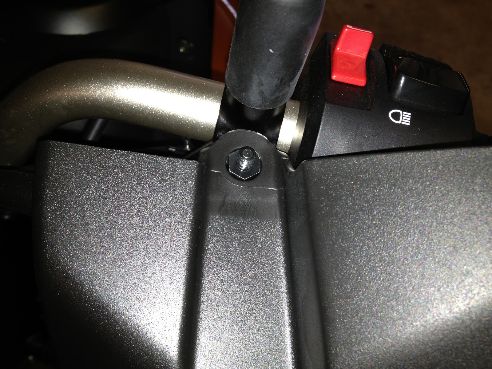
Loosen the screw holding the bar end weight, but do not remove the screw completely.  You only need to loosen the screw enough so that you can pull the whole bar end weight assembly from the handlebar.  If you do remove the screw all the way, it is quite likely that you will push the nut further into the handlebar, making it very difficult to remove.  I actually learned this lesson the hard way when I was helping a friend install these on his '09 V-Strom.

Bar End Weight Assembly Removed
Tools Used:
  • Phillips Head Screw Driver
  • 10mm socket
  • Adjustable Wrench
Time to Install: ~1 hour

Starting with the left (clutch) side, I removed the clutch lever pivot pin by first removing the nut and then unscrewing the pivot pin.  From what I can tell, the nut on the bottom primarily serves to lock the pivot pin in place, but should the nut come off for whatever reason, the pivot pin would not simply pull free.  The stock pivot pin will not be re-used.

Clutch Pivot Pin Nut
With the pivot pin removed, it's a simple matter of rotating it so that the clutch cable comes out of the groove in the end of the lever, freeing the cable stop.

End of the Clutch Lever where the cable inserts.
The next step is to remove the cable from the lever mount and tension adjuster.  I removed the tension adjuster completely by unscrewing it from the lever mount, but as it turns out, this was not necessary.  All you really need to do is line up the slots to pull the cable free, and then pull the cable housing from the end of the adjuster screw.  By not removing the adjuster, you won't have to re-adjust the tension on the clutch cable when you re-assemble everything.

Clutch Cable Adjuster with grooves lined up.
Cable housing inserts at the top.
With the clutch cable free, remove the stock boot and replace it with the boot included with the Hand Guards.  The stock boot will not be re-used.

Clutch Cable with new boot.
Using the replacement clutch-side pivot pin, re-assemble the clutch lever.  (Be sure you press in the sensor switch before you try inserting the clutch lever, or it will not go in.  This is the safety switch that will prevent you from starting the engine unless the clutch lever is pulled in.)  The replacement pivot pin will screw in just like the stock pivot pin.  The washer and spacer go on the bottom side of the lever.  Re-use the stock nut.  There isn't any need to use Locktite as the nut has an e-clip to prevent it from backing off.

Clutch-side Replacement Pivot Pin
Note the spacer that only goes on this side.
Replacement Pivot Pin installed 
Washer, Spacer, and Stock Nut
With the replacement pivot pin in place, it is time to install the clutch-side hand guard.  Before doing so, you need to remove the bar end weight assembly as described above.  Loosen the screw about 4 turns, just enough to ease the pressure on the compression nut.  Then work it side-to-side while pulling on the weight until it pops out.  It took a good amount of pulling before mine came out.  Now disassemble the bar end weight assembly completely, and re-assemble it using the included screw, which is much shorter than the stock screw.  Insert the screw into the bar end weight, then slide on the included spacer with the smaller diameter end towards the weight, then the stock washer and finally the stock compression nut.  The stock screw and aluminum sleeve spacer will not be re-used.  Insert the newly re-assembled bar end weight assembly into the handlebar but do not tighten yet.

Re-assembled Bar End Weight Assembly
Take the left (clutch) side hand guard, and mount it on the pivot pin.  There's a hole in the top that goes over the top of the pivot pin, and a slot that will go around the bottom of the pivot pin.

Top of Clutch-side Hand Guard
Secure the top of the hand guard using the included washer and cap nut.  The outside of the hand guard will snap into place in the groove provided by the smaller end of the spacer.  With the end of the hand guard snapped into place, tighten the bar end weight assembly screw to tighten the compression nut, holding the assembly in the handle bar.

Bar End Weight Assembly with Hand Guard
Finally, secure the bottom of the hand guard to the pivot pin using the supplied washer and nut.  Again, this nut has an e-clip in it to prevent it from back off by itself.

Installing the right (brake) side hand guard is essentially the same process, so I won't go into the whole process again.  This side is actually easier, because you do not have to remove any cables, just replace the pin on the brake lever.  The key difference is that the replacement pivot pin is different and uses a screw to secure the top of the hand guard.  The top is a little crowded due to the cable assembly, but I was able to rotate them upward enough to remove the stock pivot pin and insert the replacement pivot pin.

Brake-side Replacement Pivot Pin Installed 
Top of Brake-side Pivot Pin with Threaded Hole for Screw 
Installing the Brake-side Hand Guard is a little trickier, because both the top and the bottom are slotted, so you have to hold the guard in place while trying to get the screw to go in.  It might be a little easier to start the screw first, but you still would have to contend with the washer.  Be sure the push the hand guard into place while tightening the screw as the screw will want to squeeze the hand guard out of position.  Do not overtighten the screw, and you shouldn't have this problem.
Screw and Washer Securing Top of Brake-side Hand Guard
Nut and Washer Securing the Bottom
The torque values on these nuts are very low, so it should be enough to tighten them until they are nice and snug.  I used my torque wrench on the first two and despite using the recommended values, I think they still may have started to strip before I even got the click.  So for the rest of them, I simply got them nice and snug.  Fortunately, we're not dealing with engine mounting bolts or anything like that.  The pivot pins are screwed in and the nuts are for locking purposes.  Even then, they're captured by the hand guards themselves and then locked into place by the nuts securing the hand guards, so I don't think there's any real danger if any of the nuts did strip.  The hand guards seem to be attached quite securely, and the levers work as well as before the installation.

The other thing I wanted to do was to raise the windshield from the stock middle position to the top position.  The wind seems to be directed towards the top 1/3 of my helmet, resulting in quite a bit of buffeting and noise.  Despite that, it's still better than what I got on my Ninja 650R, which was the air blast directed at my shoulders and a lot of noise from under the helmet and from being totally in the air flow.

Tools Used:
  • 3mm Hex Driver
Time to Install:  ~ 10 minutes


Removal is a simple matter of loosening the four screws using a 3mm hex driver and pulling the wind shield free.

Windshield Removed
After removing the windshield, I removed the four plugs from the top position holes.  It took a bit of prying around the edges, but they finally came free.
Rubber Plug
Next, I removed the well nuts from the stock middle holes and moved them to the top holes.  I found that they came out and inserted quite easily using a twisting motion.

Well Nut
All that was left to do was position the windshield over the well nuts and tighten the screws.  I finger-tightened them first, centered the windshield, and then tightened the screws until they were snug.  I gave the windshield a good push on the sides to make sure it wasn't going to shift positions.  And that completes the major modifications to the V-Strom for now.

I rolled it out onto the driveway to take a picture in the bright sunshine.


After a couple of rides, I find that I do like the hand guards and new windshield position.  I think they even help with the air flow and noise a little, but it's hard to tell for sure since I also raised the windshield after installing the hand guards.  The air flow seems to have improved with the raising of the windshield.  The noise and buffeting do not seem to be as bad is it was previously, and if I duck my head down a few inches, it all but disappears completely.  I may look into installing one of the MRA X-creens with that extra wing to see if that does the same thing.  That will be a nice change from what I've been used to.

And with that, the only things left to do are to install the brake light wiring for the Givi Maxia 3 and the RAM Mounts for my POV camera.  That will be covered in another posting.

Thursday, November 15, 2012

Givi Maxia 3 Top Case and Mounting Plate

After installing the lower cowling (see previous post), I turned my attention towards mounting the Givi top case.  I opted for the Maxia 3 Luxury B model, which boasts 55L of storage volume and includes the case liner and integrated brake lights.  The best price I found was at Twisted Throttle for $359.10.  I understand that there are performance issues surrounding the brake lights and connectors, but I would have only saved $25 had I purchased the base Maxia 3 and case liner separately.  There are also options if I find that the brake light situation isn't serviceable, such as hardwiring the lights from the bottom case contacts or installing the Admore upgrade, which even adds running lights and turn signals to the case.  I'm holding off on that option for now, since it's a $140 upgrade.

Tools Used:
  • Rubber Mallet
  • Socket Extension
  • X-acto Modeling Knife
  • Socket: 10mm, 13mm
  • Hex Driver: 5mm
  • Ratchet
  • Philips Head Screw Driver
Time to Install:  ~1 hour thanks to having to find some missing tools.

So to start off, I had to remove the blank from the adapter plate to open the hole where the contact for the power supply mounts.  It was pretty simple to do using a rubber mallet and the extension from my socket set.  I put the 3/8" square driver end on the plate, and struck the socket end with the mallet.  After about 5 good hits, the blank broke off.  I then cleaned up the hole using an X-acto modeling knife.

View from Bottom of Plate 
View from Top of Plate 
Socket Extension and Mallet
The next step is to install the Givi mounting plate.  This is the SR3101 plate for mounting Monokey boxes to the 2012 DL650A V-Strom.  First, you remove the OEM rubber cover from the rack.  There are five (5) "plugs" on the bottom of the pad that are simply press-fit to hold the cover on.

Rubber Pad Removed
Removing the pad reveals the two bolts that hold on the luggage rack.  Use the 13mm socket to remove these bolts.  You can put these aside as they will not be re-used.
Mounting Bolts at Top
The mounting plate comes with two metal spacers that will go into the holes where the original mounting bolts were.  Be careful and check the spacers.  One of mine still a metal shaving attached from when the holes were bored out, and the spiral shaving was very sharp.  I used one of the bolts to push it through.
Spacer (L), Metal Shaving (R) 
Spacers in the Luggage Rack Holes
With the spacers in place, you put the SR3101 mounting plate on the rack, and attach it using the 5mm hex driver to drive the supplied bolts.  The two longer bolts go where the original luggage rack bolts were (towards the front of the bike), and the two shorter bolts go in the holes towards the rear of the bike and secure with the included nylock nuts.  You will need the 13mm socket to hold the nut.  Unfortunately, I forgot to take a picture of the plate mounted by itself, but you'll be able to see it in one of the next pictures.  So with the mounting plate installed, it's time to install the adapter plate to which the top case actually mounts.  I wasn't sure how far back I wanted to install it, so I put the case on it and dry-fitted it first.  I started with it all the way to the rear, but it looked a bit odd to me, so I moved it one square forward, and it seemed a little better.  I may have to move it back if my wife decides she wants to ride with me, because the case might be a little too far forward in that case.  Moving it back would give about another 1-1/2" of room.

Test Fitting the Adapter Plate and Case
In the picture below, you can see the adapter plate as mounted to the SR3101 mounting plate.  The SR3101 plate has four (4) studs to which the adapter plate connects, using the four square shaped washers and provided nylock nuts to hold it in place.  You will use the same 10mm socket to tighten the nuts.  As you can see, I mounted the plate one square forward of the rearmost position, and then I slid the plate as far back as the washers would allow.

Adapter Plate Mounted to the SR3101 Mounting Plate
After that, it's a simple matter of snapping the cover on and fixing it in place using the four (4) provided screws.  These screws are tiny, so make sure you don't lose them when you open the bag.  Do not screw them in too tight either, as they can easily strip the holes.

Mounting Plate/Adapter Fully Installed
Note the hole for the power connector. 
Side View 
With Case Mounted
I just received the brake/tail/signal wiring harness that I ordered from Eastern Beaver.  This will allow me to simply unplug the rear brake/tail/signal light harness, insert this adapter harness, and then use the open lead to wire in the Givi brake lights.  I bought additional plug housings so that everything is a plug-in connection, which will be a lot cleaner than positaps or splicing.  If I do decide to get the Admore kit, I can just unplug the Givi lead, and then install a plug on the Admore harness and plug it right in.  That and installing the OEM hand guards will probably be this weekend's project.

Wednesday, November 14, 2012

Suzuki OEM Under Cowling and Tank Pad

So last week my remaining two packages arrived -- one containing my Givi Maxia 3 topcase and mounting plate, and the other the Suzuki OEM under cowling, hand guards, and tank pad.  This posting will cover the installation of the under cowling and tank pad.  The latter will pretty much consist of a picture of the finished installation since it's not exactly rocket science.

Many people say that the OEM under cowling isn't worth it, because it doesn't protect the bottom of the bike, is made of plastic, and costs as much as a metal skid plate.  While I do admit that it was a bit of a mental struggle to justify its cost, it suits my needs since I don't plan on doing any off-road riding that would require the additional weight of a metal skid plate.  I just wanted something to protect the oil filter and the front exhaust header that didn't add a lot of weight to the bike.  I considered the Givi belly pan but I think the OEM under cowling integrates with the bike's overall look better.  The best price I found was at www.OneidaSuzuki.com, and they were able to get it to me in 5 days despite being in the path of Superstorm Sandy.

This is a very simple installation, and the Suzuki installation instructions are actually quite good.  Even so, I still find it helpful to have pictures of the actual parts.

Tools Used:
  • Philips Head Screw Driver
  • Sockets: 8mm, 10mm
  • Ratchet
  • Hex Driver: 5mm
  • Torque Wrench
Time to Install:  ~45 minutes


Center/Front and Right pieces fitted together.
Left piece ready to be fitted.
The under cowl comes in three pieces (left, center/front, right), individually wrapped in foam padded sleeves.  These foam sleeves served a nice dual purpose as layout mats for keeping the parts off of the floor.  The three pieces snap together, which I discovered unintentionally as I was checking their fit, and then secured on either side of the center/front piece by three screws.

The tab from the side piece snaps over the screw post on the center/front piece . 
Notice that the two top screws are shorter than the four bottom screws. 
Here's how it looks fully assembled.
The installation kit includes a neoprene pad that attaches to the under cowling at the top-center.  The pad is peel-and-stick, so it's simply a matter of locating it per the instructions and sticking it on.


There are four (4) rubber grommets that go into the holes where the under cowling connects to the mounting brackets.  It's easiest to insert them from the inside of the cowl by squeezing them flat and inserting the end of the grommet onto the edge inside the hole.  Then it's just a matter of pushing the rest of the grommet in and making sure the sides lay flat on the inside and outside.  There are four (4) aluminum sleeves that then get inserted into each grommet, but I decided not to put those in until I was ready to mount the cowling to the bike.


Now that the under cowling is assembled, it's time to install the mounting brackets on the bike.  The front bracket mounts to two stand-offs on the front cylinder housing using the 10mm socket to drive the two provided bolts.  Be sure to install it with the bar above the bolts as shown below.

The stand-offs are just below the exhaust connection.
Front bracket installed.
Front bracket mounting point.
The lower/side brackets are mounted using the 8mm socket to drive the existing bolts from the clutch cover and generator cover.  The brackets are stamped with "L" and "R" even though it's fairly obvious which one goes where.  The installation instructions say to torque all of these bracket bolts to 10 N-m / 7.0 lbf-ft.

Right side (Clutch) bracket with "R" stamp.

Left side (Generator) bracket with "L" stamp.
Now that the brackets are installed, it's time to mount the under cowling.  Before doing so, it's time to insert the aluminum sleeves into each of the four (4) rubber grommets in the cowling.  It's a simple matter of working it into the opening and sliding it in until it's flush on both sides.


If you are working on the bike with it on the side stand, you will want to start mounting the cowling from the right side.  If you start on the left side, the cowl will want to rotate out under the bike thanks to gravity and flex at the bolt holes.  It seems as though the material is sturdy enough to not crack or anything, but why risk it?  By starting on the right side, it will simply hang on the bolts without any flexing.  I snugged everything up on both sides using the 5mm hex driver and then torqued the bolts according to the installation instructions to 7 N-M / 5.0 lbf-ft.  And here it is installed:


The tank pad installation is quite tricky.  Not.  The package comes with an alcohol wipe with which you can clean the surface.  Then it's simply a matter of eye-balling it where you want to put it.  Again, this is a little more expensive than other aftermarket tank pads, but I like the factory look of it.  Now that I look at it again, I wish I had put it a little further up towards the warning stickers.  Oh well.  It also reminds me that I need to bust out the hair dryer and remove those.

UPDATE:  With regard to removing the stickers, I ended up just letting the bike sit out in the summer sun for about 30 minutes, and that was enough to allow me to gently peel them off without leaving any residue behind.


So that's the OEM Under Cowling and Tank Pad.  Next up is the Givi Maxia 3 top case and mounting plate.