As I mentioned in the previous post, I decided that I would go with frame and swing arm sliders for protection against damage incurred due to the ever-lurking dirt nap. I haven't completely dismissed the possibility of installing crash bars, but for now the sliders will be sufficient. So after trading a few emails with Blair Layton, I bought the combo package from him at his site, SVRacingParts.com, for $134.90 shipped. This price includes the upgrade to black anodized parts to match my V-Strom's frame color. (Blair was very helpful and answered every question I had and even offered some sage advice. Give him a shout, you won't be disappointed.) I submitted the order on Monday and received on Wednesday. It doesn't get much better than that without paying out the nose for next day delivery. I was going to wait until the weekend to install these, but I'm planning on burning off some more break-in miles tomorrow, and it would be just my luck to have my new bike take a dirt nap while the sliders are safe at home. So out came the parts and tools. Please note that the list below contains the tools I actually used. Some were not ideal, but they worked. I'll expand on this later.
Tools used:
- 2 - 17mm socket wrenches
- 1 - ruler (you won't need one, because I used one already)
- 1 - medium adjustable monkey wrench
- 1 - pair of channel locks
- 1 - 6mm hex driver
- Blue Locktite
Time required: ~45 minutes

So opening the box revealed the parts, nicely packed away in plastic bags. There was the replacement through bolt in its own bag, the miscellaneous parts individually sealed in a series of bags, the slider "pucks" with their mounting hardware also individually sealed in a series of bags, and the swing arm sliders on a shrink wrapped card. The parts all look very well made with clean edges and no sloppiness about them. So far so good. After a quick read through the instructions, I gathered my tools and parts and headed into the garage.
I have to admit that around this time I started to have second thoughts about the whole process, because it just hit home that I was about to remove the through bolt that holds the engine in the frame. What if the engine dropped out while I was swapping through bolts? Surely Blair would have mentioned something about this possibility. In the end, it was all a non-issue. I'm not sure exactly how the engine is mounted since I don't have a service manual yet, but it does not solely depend on that through bolt.
Step 1: Remove the OEM Through Bolt and Insert the SV Racing Parts Replacement Bolt
Obviously, the first thing that needs to be done is to remove the existing through bolt. You'll need two (2) 17mm sockets. Wrenches won't work, because the bolt and nut are recessed in the frame. The bolt in question is at the bottom of the V-shaped bracket in the pictures below.
It took a bit of muscle to break the nut loose as one would expect, but it shouldn't require a cheater bar or anything drastic. I initially heard some interesting noises, as if something were cracking. I even stopped to inspect my ratchet handles to make sure they hadn't failed. They were fine, and after about 1/8 turn, the nut started turning smoothly. Once the nut came loose, I put it back on just enough to keep the bolt from escaping on its own, since the head of the bolt is on the left, and thus downhill, side. I don't have a center or pit stand, so the bike is leaning on the side stand.
Obviously, the first thing that needs to be done is to remove the existing through bolt. You'll need two (2) 17mm sockets. Wrenches won't work, because the bolt and nut are recessed in the frame. The bolt in question is at the bottom of the V-shaped bracket in the pictures below.
 |
| Left Side (as seated) |
 |
| Right Side (as seated) |
 |
| Close-up of Loosened OEM Nut (Right Side) |
I then took the replacement through bolt and screwed one of the kit's posts on one end to keep the bolt from sliding all the way through. (The posts are the two large cylindrical pieces in the lower right corner of the parts picture above. They have threaded holes in each end with one end flattened on either side.) There's enough friction to keep that from happening, but I figured I'd play it safe. After removing the nut, I pulled the OEM bolt out just enough to give me room to insert the replacement bolt. Once I did that, it was a simple matter of pulling out the OEM bolt while feeding in the replacement bolt. As it turns out, the OEM nut is held in place with an e-clip, which is what was making those noises at the beginning. You can just see it in the picture below.
 |
| Nut with e-clip inside |
Step 2: Center the Replacement Bolt
Here is where I used the ruler and why you won't need to. Being the selectively OCD person I am, I removed the kit post from the through bolt and then pushed it from the left side until the left end was flush with the frame. I measured how much of the bolt was exposed on the right side of the bike so I could determine how much bolt should be exposed on each side to center it. As it turns out, there was slightly under 2-1/2" showing, which meant that there needed to be 1-1/4" on each side. Now you know, too. And knowing's half the battle. Go Joe! (Sorry, I don't know where that came from.)
 |
| Measuring the Exposed Portion of the Replacement Bolt |
 |
| 1-1/4" Exposed on the Left Side |
The kit comes with two spacers that go into the recesses on either side of the bike. They are labeled "Left" and "Right" on the bags. Be sure to note which is which. Fortunately, the large spacer will not fit on the right side of the bike, so if you start with the right side, you can't screw it up.
 |
| Spacers, Washer and Posts Fitted Together for Reference |
 |
| See? Too Big (Left Spacer on Right Side) |
I put the small spacer on the right end of the bolt, then used enough blue Locktite to cover the exposed threads. Don't skimp on the Locktite and do be sure to put a paper towel or shop rag underneath to catch any excess runoff. After that, it was a simple matter of screwing on one of the kit posts. I only tightened the bolt until it just started to bump up against the spacer so it wouldn't shift the bolt off-center. The bolt goes on with the flattened end away from the bike. It will only go on one way, but this tip will save you the trouble of trying to put it on the wrong way first like I did. It should look like this:
 |
| Right Side Spacer and Post |
 |
| Right Side Assembled |
 |
| Left Side Assembled |
Blair's instructions say to tighten the posts such that they are "Good and Snug" against each other and to let the blue Loctite do its job. Avoid the urge to "go Gorilla and give it one more good big Umphhhh..."
Remember, Blue Loctite is your friend, be generous and use it on all bolt threads.
I usually like to work with torque values when tightening bolts and such, but Blair's instructions seemed reasonable. That, and I don't have a torque wrench that could fit these posts anyway. I figure that I'll check them before each ride anyway to make sure that they're not making any unapproved vacation plans.
Step 4: Attaching the Pucks
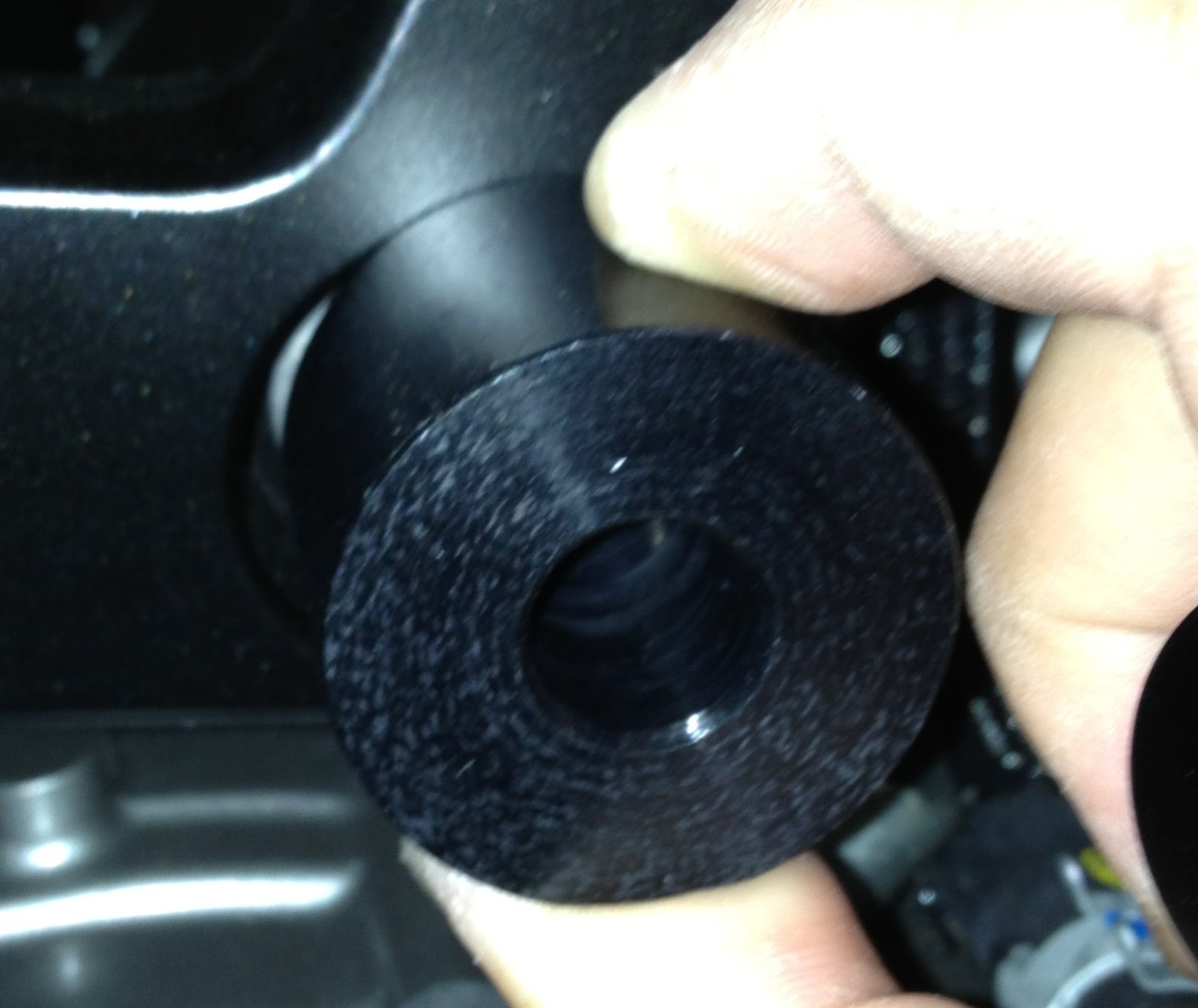
This part is very easy since each puck comes individually bagged with all of the hardware in place and ready for assembly. Just don't drop them or slide them out of the bag without being ready to catch them with everything in place. You're going to need a 6mm T-handle, Allen Wrench or Hex Driver to do this. I'm not sure a socket hex driver will work, because the hole in the puck may not be of a sufficient diameter for it to fit.
 |
| Bolt Inside of the Puck |
I used a Hex Driver for this part. In order to get the blue Loctite on the threads, I found it easiest to insert the Hex Driver into the bolt head and hold the puck up at an angle somewhat like an ice cream that's dripping. This allowed me to get my little tube of blue Loctite in there to bathe the threads without the bolt dropping out the other end. In the picture below, I'm holding the bolt in with my finger, but you get the idea.
 |
| Bolt Threads Inside the Other End of the Puck |
With the bolt bathed in blue Loctite, it was a simple matter of screwing the puck assembly to the post on each side of the bike. The same Good and Snug principle applies.
Remember the Gorilla, Good and Snug and stop. Blue Loctite will not allow the bolts
to losen or back out without direct effort. Trust your friend Blue Loctite, it will hold.
And just like that, the frame sliders are installed. Here's what it looks like.
Step 5: Installing the Swing Arm Sliders
 |
| Right Side Completed |
 |
| Left Side Completed |
This is pretty much exactly the same as installing the frame slider pucks, using the same 6mm T-Handle/Allen Wrench/Hex Driver. The mounting points are on the bottom side of the swing arm on either side just forward of the rear wheel axle. You can't miss them. Use plenty of blue Locktite, remember the Gorilla, and Good and Snug.
IMPORTANT: In the first picture below, you will notice that the washer is on the end of the bolt. This is the way it came out of the packaging, but it is not where it should be installed. You need to remove the washer, remove the bolt from the puck, then install the washer inside the puck, and run the bolt through the washer and then the puck. The bolt head itself will only secure the aluminum sleeve. The washer secures the puck. So without the washer, there is a very good chance the puck will not stay on the aluminum sleeve over time. I thought I saw a washer inside and installed it as-is, but after checking this morning, I found that I had not installed it properly. Lesson Learned: RTFM and check and double-check. Thanks, Blair, for catching that.
IMPORTANT: In the first picture below, you will notice that the washer is on the end of the bolt. This is the way it came out of the packaging, but it is not where it should be installed. You need to remove the washer, remove the bolt from the puck, then install the washer inside the puck, and run the bolt through the washer and then the puck. The bolt head itself will only secure the aluminum sleeve. The washer secures the puck. So without the washer, there is a very good chance the puck will not stay on the aluminum sleeve over time. I thought I saw a washer inside and installed it as-is, but after checking this morning, I found that I had not installed it properly. Lesson Learned: RTFM and check and double-check. Thanks, Blair, for catching that.
Tip: Before bathing the bolts in Loctite, hand thread them into the threaded holes on the swing arm to make sure there isn't anything obstructing the threads. I had no problem with the left side, but when I did this on the right side, there was some resistance until I got past the first thread or two. Just be careful not to cross-thread them.
 |
| Swing Arm Slider Bolt Threads |
 |
| Swing Arm Slider Bolt Head |
 |
| Left Side Installed |
 |
| Right Side Installed |
Job Complete
All that's left to do is clean up. The sliders look really good on the bike and seem very sturdy. I hope I never have the occasion to tell Blair just how much damage they prevented to the bike itself. Another benefit of the frame sliders is that I think I can purchase a RAM mount that can attach to one of the posts so I can mount my Drift Stealth HD 170 POV cam. I'll have to look into that further. That's it for this episode. Tomorrow, I ride!
Great help since I had lost the instructions. Thanks,
ReplyDeleteArt
Glad you found it helpful!
Delete